07. 31. 2026
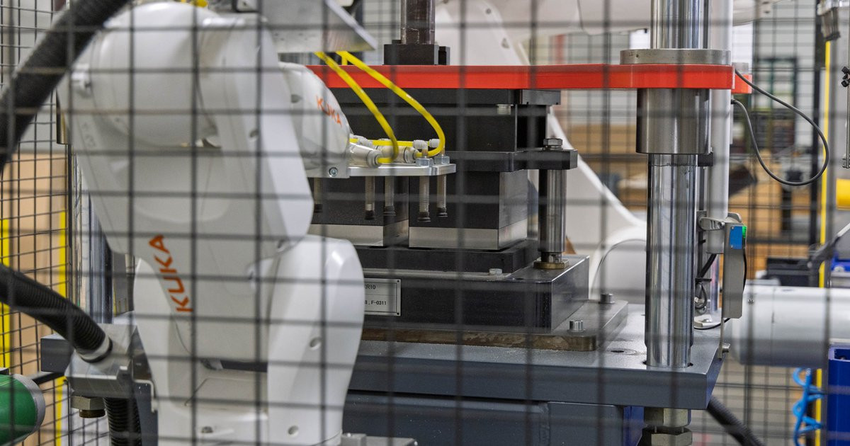
Equipment design determines molded fibre quality through three critical engineering systems: forming tool precision (±0.15 mm tolerances), press platen temperature uniformity (±3°C distribution), and pulp distribution control. European procurement managers sourcing premium non-food packaging face dimensional variation, surface finish inconsistency, and production waste when production lines lack integrated design control over these systems. Equipment manufacturers who design forming tools, hydraulic systems, and process control as separate components cannot achieve the mechanical repeatability required for cosmetics, electronics, or fragrance packaging specifications.
Equipment design in molded fibre production comprises four integrated mechanical systems: the forming station where pulp suspension contacts the forming tool, the transfer mechanism moving wet pre-forms between stations, the heated press where final shaping and dewatering occur, and the process control architecture managing temperature, pressure, and timing across all stations. Each system directly affects final part quality through specific physical mechanisms.
Forming tool precision determines dimensional accuracy and surface finish. Tools manufactured to ±0.15 mm tolerances produce parts meeting cosmetics packaging specifications for lid-to-base fit and electronics packaging requirements for component retention geometry. Surface finish results from tool cavity surface treatment: electroformed nickel surfaces achieve 20–40 micrometres Ra roughness suitable for direct retail presentation, whilst machined aluminium tools produce 60–100 micrometres Ra suitable for protective packaging applications.
Press platen design controls temperature uniformity across the heated die surface. Temperature variation above ±3°C between cavity positions creates inconsistent dewatering rates, producing wall thickness variation that fails quality inspection. Platen thickness, heating element distribution, and thermal mass design determine whether multi-cavity tools achieve uniform compression across all positions simultaneously.
Pulp distribution systems affect fibre density uniformity through vacuum distribution design and former geometry. Uneven vacuum draw creates basis weight variation between cavities in multi-cavity production. Distribution manifold design, vacuum pump capacity, and former perforation patterns must match to achieve ±5% basis weight consistency across cavity sets.
Process control integration determines production consistency over shift duration and between operators. Equipment using separate controllers for hydraulic pressure, platen temperature, and cycle timing requires manual coordination that introduces operator-dependent variation. Integrated control systems with programmable logic controllers eliminate manual adjustment points and maintain parameter consistency regardless of operator experience level.
| Design aspect | Integrated equipment design | Component-assembly approach |
|---|---|---|
| Forming tool manufacture | In-house tooling workshop with iterative testing capability | External tooling supplier with 12+ week lead times |
| Press system integration | Hydraulic system designed for specific platen thermal characteristics | Standard hydraulic press adapted with heated platens |
| Control architecture | Single PLC managing forming, transfer, pressing, ejection timing | Separate controllers requiring manual synchronisation |
| Commissioning process | Factory acceptance testing with production-representative trials | On-site commissioning resolving interface issues between suppliers |
| Modification capability | Design changes tested in-house before customer deployment | Modifications require coordination between multiple external suppliers |
| Spare parts availability | Critical components manufactured in-house with documented specifications | Spare parts sourced from original suppliers with extended lead times |
European procurement managers evaluating molded fibre packaging suppliers should assess equipment design capability as primary qualification criteria before requesting samples or quotations. Suppliers operating equipment from external manufacturers face mechanical constraints that limit their ability to match packaging specifications requiring tight dimensional tolerances or premium surface finish. The question is not whether the supplier has experience with your product category, but whether their equipment design enables the mechanical precision your application requires.
Dimensional tolerance capability determines packaging functionality in applications where molded fibre components interface with injection-moulded parts, printed paperboard sleeves, or product retention geometry. Cosmetics packaging requiring lid-to-base fit within 0.3 mm, electronics packaging holding components with anti-rotation features, and fragrance packaging with precision insert cavities all depend on forming tool accuracy and press alignment that component-assembly equipment approaches cannot reliably achieve. Request tool tolerance specifications and press alignment verification procedures during supplier qualification.
Surface finish consistency affects both aesthetic presentation and functional printing requirements. Premium applications in cosmetics, audio equipment, and fashion accessories require surface finish uniformity across production runs to maintain colour consistency after printing and coating. Equipment lacking integrated temperature control produces surface texture variation that becomes visible after UV coating or foil stamping. Examine production samples from multiple production dates and request surface roughness measurement data before committing to tooling investment.
Production flexibility matters when product specifications change during commercialisation or when packaging formats evolve across product ranges. Suppliers with in-house tooling capability can modify cavity geometry, adjust wall thickness distribution, or redesign rib structures within 4-week cycles. Suppliers dependent on external tooling suppliers face 12+ week modification cycles that delay product launches and increase inventory risk during format transitions. Assess tooling modification lead times and design iteration capability during technical discussions.
TRIDAS designs and manufactures its own molded fibre production lines at its Czech facility, integrating forming tool design, hydraulic press engineering, and process control development under one engineering team. This integrated approach enables iterative testing of tool geometry modifications and press parameter optimisation before customer equipment commissioning, reducing on-site installation time and eliminating cross-supplier compatibility issues. In-house tooling manufacture delivers approximately 4-week lead times from design approval to production-ready cavity sets, enabling faster commercialisation cycles for European brands moving from plastic to molded fibre packaging in cosmetics, electronics, and premium consumer goods categories.